Foreign key constraints are supported for the
InnoDB storage engine only. For other storage
engines the foreign key syntax is correctly parsed but not
implemented. For more information see
Section 1.8.5.4, “Foreign Key Differences”.
Using MySQL Workbench you may add a foreign key from within the table editor or by using the relationship tools on the vertical toolbar of an EER Diagram. This section deals with adding a foreign key using the foreign key tools. To add a foreign key using the table editor see Section 16.6.7.1.3.5, “The Foreign Keys Tab”.
Using the graphical tools to add foreign keys is most effective when you are building tables from the ground up. If you have imported a database using an SQL script and do not need to add fields to your tables you may find it more effective to define foreign keys using the table editor.
There are six foreign key tools on the vertical toolbar on the left side of an EER Diagram. These tools are:
The
one-to-one non-identifying relationshiptoolThe
one-to-many non-identifying relationshiptoolThe
one-to-one identifying relationshiptoolThe
one-to-many identifying relationshiptoolThe
many-to-many identifying relationshiptoolThe
Place a Relationship Using Existing
            Columns
tool
An identifying relationship is one where the child table cannot be uniquely identified without its parent. Typically this occurs where an intermediary table is created to resolve a many-to-many relationship. In such cases, the primary key is usually a composite key made up of the primary keys from the two original tables. An identifying relationship is indicated by a solid line between the tables and a nonidentifying relationship is indicated by a broken line.
Create or drag and drop the tables that you wish to connect. Ensure that there is a primary key in the table that will be on the “one” side of the relationship. Click on the appropriate tool for the type of relationship you wish to create. If you are creating a one-to-many relationship, first click the table that is on the “many” side of the relationship, then on the table containing the referenced key.
Doing this creates a field in the table on the many side of the
relationship. The default name of this field is
table_name_key_name where the table
name and the key name are both derived from the table containing
the referenced key.
When the many-to-many tool is active, double-clicking a table creates an associative table with a many-to-many relationship. For this tool to function there must be a primary key defined in the initial table.
Use the , menu item to set a project-specific default name for the foreign key column (see Section 16.6.5.1.5.4, “The Relationship Notation Menu Option”). To change the global default see Section 16.4.4.4, “The Model Tab”.
To edit the properties of a foreign key, double-click anywhere on the connection line that joins the two tables. Doing this opens the relationship editor.
Mousing over a relationship connector highlights the connector and the related keys as shown in the following figure.
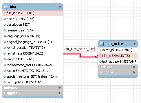
The film and the film_actor
tables are related on the film_id field and
these fields are highlighted in both tables. Since the
film_id field is part of the primary key in the
film_actor table, a solid line is used for the
connector between the two tables.
If the placement of a connection's caption is not suitable, you
can change its position by dragging it to a different location. If
you have set a secondary caption, its position can also be
changed. (For more information about secondary captions see
Section 16.6.7.2.3, “The Properties of a Connection”. Where the notation
style allows, Classic for instance, the
cardinality indicators can also be repositioned.
The relationship notation style in Figure 16.48, “The Relationship Connector” is the default, crow's foot. If you are using a commercial version of MySQL Workbench you can change this. For more information, see Section 16.6.5.1.5.4, “The Relationship Notation Menu Option”.
You can select multiple connections by holding down the Ctrl key as you click a connection. This can be useful for highlighting specific relationships on an EER diagram.
Double-clicking a relationship on the EER diagram canvas opens up the relationship editor. This has two tabs: Relationship, and Foreign Key.
The Relationship tab
In the Relationship tab you can set the
caption of a relationship using the Caption
text box. This name displays on the canvas and is also the name
used for the constraint itself. The default value for this name is
fk_.
Use the ,
menu item to set a project-specific default name for foreign keys.
To change the global default see
Section 16.4.4.4, “The Model Tab”.
source_table_destination_table
You can also add a secondary caption to a relationship and also a comment.
The Visibility Settings frame is used to
determine how the relationship is displayed on the EER Diagram
canvas. Fully Visible is the default but you
can also choose to hide relationship lines or to use split lines.
The split line style is pictured in the following:
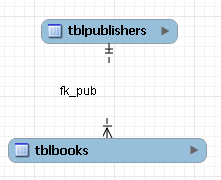
A broken line connector is used to indicate a nonidentifying relationship. The split line style can be used with either an identifying relationship or a nonidentifying relationship. It is used for display purposes only and does not indicate anything about the nature of a relationship.
To set the notation of a relationship go to the , menu item. For more information, see Section 16.6.5.1.5.4, “The Relationship Notation Menu Option”.
The Foreign Key tab
The Foreign Key tab contains several frames: Referencing Table, Cardinality and Referenced Table.
The Mandatory checkboxes are used to select
whether the referencing table and the referenced table are
mandatory. The default value for both of these constraints is
true, which is indicated by the checkboxes
being checked.
In the Cardinality frame there is a set of radio buttons that allow you to choose whether the relationship is one-to-one or one-to-many. There is also a checkbox that enables you to specify whether the relationship is an identifying relationship.
To select a connection, right-click it. When a connection is selected it is highlighted and its properties are displayed in the properties palette. The properties of a connection are quite different from the properties of other objects. These properties are described in the following list:
caption: The name of the object. By default this property is centered above the connection line. Its default value is the name of the foreign key.captionXOffs: The “x” offset of the caption.captionYOffs: The “y” offset of the caption.comment: The comment associated with the relationship.drawSplit: Whether or not to show the relationship as a continuous line.endCaptionXOffs: The “x” termination point of the caption offset.endCaptionYOffs: The “y” termination point of the caption offset.extraCaption: A secondary caption. The default location for this extra caption is centered beneath the connection line.extraCaptionXOffs: The “x” offset of the secondary caption.extraCaptionYOffs: The “y” offset of the secondary caption.mandatory: Whether or not the entities are mandatory. For more information, see Section 16.6.7.2.2, “The Relationship Editor”.many: False if the relationship is a one-to-one relationship.middleSegmentOffset: The offset of the middle section of the connector.modelOnly: when this is set the connection will not be propagated to the DDL. It is just a logical connection drawn on a diagram. This is used, for example, when drawing MyISAM tables with a visual relationship, but with no foreign keys.name: The name used to identify the connection on the EER Diagram canvas. Note that this is not the name of the foreign key.referredMandatory: Whether or not the referred entity is mandatorystartCaptionXOffs: The start of the “x” offset of the caption.startCaptionYOffs: The start of the “y” offset of the caption.
In most cases you can change the properties of a relationship
using the relationship editor rather than the
Properties palette.
If you make a relationship invisible by hiding it using the relationship editor's Visibility Settings, and then the relationship editor is closed, you will no longer be able to select the relationship to bring up its relationship editor. To make the relationship visible again you will need to expand the table object relating to the relationship in the Layers palette and select the relationship object. Once selected, you can edit the object by right-clicking, and selecting . You can then set the Visibility Settings to Fully Visible. The relationship will then be visible in the EER Diagram window.